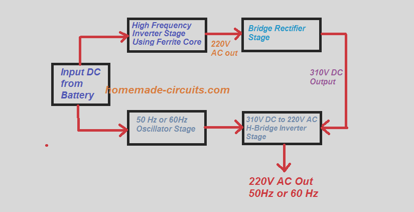
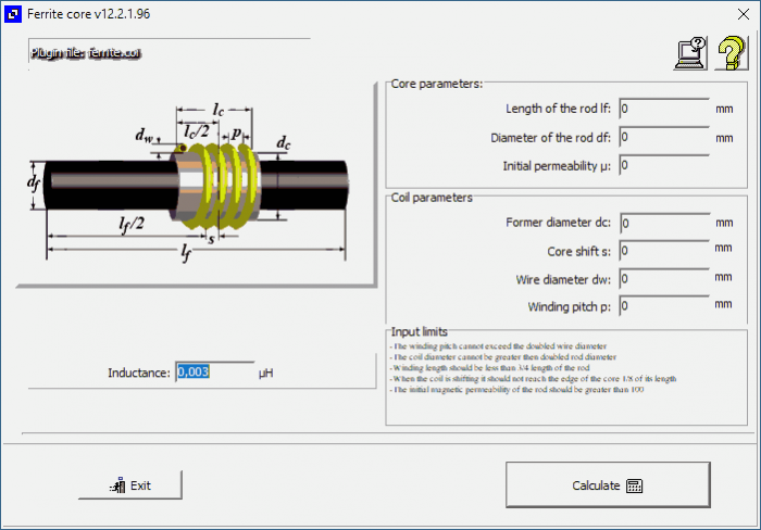
In this article you will learn how to calculate turns ratio of ferrite core transformer for high frequency switch mode power supply inverters. High ferrite core transformers are used in almost every power electronics circuits like inverters and pure sine wave inverters.They are used to boost up or step up low dc voltage of battery and other dc sources like solar panels. Download Leaflet ( 70 Kb ) To Download Demo - Click Here. This is a windows based software for designing small transformers working on Line Frequency (50 / 60 Hz) and High Frequency for use in SMPS. The Line Frequency Transformers are divided into two categories,. Ordinary Transformers for use in Linear Power Supplies, Inverters etc.
|

Magnetics Designer is a standalone software program for Windows that designs all types of layer (and sector/split bobbin) wound transformers and inductors, and generates a corresponding SPICE model. Magnetics Designer produces a complete transformer or inductor design based upon electrical specifications, including a winding sheet report and a SPICE-compatible model with parasitics. A database with thousands of cores, wide variety of materials and wire is included, including a non-linear saturable core SPICE model. In addition, you can add your own cores, wire and material information using a supplied Excel© spreadsheet. Core vendors such as TDK, Magnetics, Philips, Thomson, Micrometals, Siemens, Kaschke, Ferrite International, VAC and Fair-Rite are represented. Further, formvar, square or double square magnet wire, Litz wire, PCB traces, or foil can be selected. Specialized wire types like those used in planar magnetics can also be added. The program predicts magnetizing and leakage inductance, inter-winding capacitance, peak flux density, DC winding resistance, high frequency AC resistance (including proximity effects and skin effect), copper loss (both AC and DC), core loss, weight, temperature rise, layer fill and window fill percentage. Typical design applications include high frequency switching regulator transformers and output chokes for off-line, full-wave and forward converters, 60 Hz single-phase line transformers, AC inductors, planar magnetics and 400 Hz aircraft transformers. Virtually any single phase, layer wound inductors or transformers that range from 10Hz to over 5MHz can be synthesized with Magnetics Designer. |
Compatibility:Windows 2000/XP/Vista/7/8/8.1, 8Meg RAM and Microsoft Excel is required if you want to edit or add to the core database. A screen resolution of 800 x 600 or better is also required. |
| Download: Magnetics Designer demo, product brochure or application note in PDF format. A FAQ document (Frequently Asked Questions) is also available. |
| Latest Magnetics Designer version: It is posted on the Magnetics Designer Support page. Current users may download the file. See What's New. |
Where was Magnetics Designer Developed? |
The Magnetics Designer software was originally developed by Analytic Artistry, the leader in the field of nonlinear magnetics design tools. In 1995, Intusoft acquired the rights to the 'Transformer and Inductor Spreadsheet,' originally a DOS-based program. Intusoft ported the Analytic Artistry product to Windows, added a number of key enhancements and changed the name to Magnetics Designer. Power supply designers with decades of real-world experience have validated the software at both companies. |
How Magnetics Designer Works? |
To start a design, you first select the core family and material. After you enter the operating frequency, the Core Wizard function will select the best core for the job. You may browse through the core database and choose an alternate core, if desired. You can lock the selected core geometry or let the program alter it during the optimization process. Finally, the electrical specifications such as voltage and current per winding are entered on the Transformer screen.
Initial Transformer Design Screen
| Optimization Summary Screen | Resulting Transformer Screenwith geometries tried & wire suggestions |
Ferrite Transformer Design
| Magnetics Designer uses proprietary algorithms to select the appropriate core, number of turns and wire size. This is done to minimize total power dissipation for a given temperature rise in the smallest possible core. The program takes into account design constraints such as the maximum allowed window fill, peak flux density and temperature rise. Once finished, Magnetics Designer will provide a summary of the cores it tried to optimize, and suggests on how to possibly improve the design if design constraints were not met. After the initial optimization pass, the transformer screen lets you change any of the more than 20 design parameters, such as number of turns; wire gauge and type; number of parallel strands; gap length; layer insulation thickness; wrapper thickness and end margin lengths. The program will analyze your changes and immediately show the calculated results each time a parameter is altered. You can easily optimize and compare several designs using different core types and materials. Once the design is complete, the winding specification and a complete electrical performance summary can be displayed or printed. |
| The Transformer Design Screen provides trade off of more than 20 different design parameters. Magnetics Designer automatically flags any design constraints that are violated. |

Switch Mode Power Supply Wizards |
Magnetics Designer contains new Switch Mode Power Supply Wizards for transformer-coupled Flyback designs and Buck regulators. Just enter the power supply specification and Magnetics Designer computes the transformer or inductor spreadsheet entries. Necessary data includes input power supply voltage; the output voltage(s) and current(s) with frequency; duty ratio and ripple current. An automatic design phase synthesizes the transformer or inductor. The user can then interact with Magnetics Designer to perfect the design. When acceptable results are achieved, an IsSpice4 model is generated for use in one of the template power supplies. This feature is available in the demo version of the Magnetics Designer program, which provides a limited number of windings and cores. |
Ferrite Core Material
Flyback SMPS Wizard
Buck SMPS Wizard
Power Supply Templates |
| A number of working power supply designs have been placed in a template framework. These templates include Flyback, Forward, and Push-Pull topologies. The demo software will run average and switching models for these pre-designed templates. The templates accept the IsSpice4 transformer models generated using Magnetics Designer for cycle-by-cycle switching simulations. The transformer parameters can be input to the 'Average' models. New 'Average' models for Forward and Flyback work for both large and small signals with auto CCM/DCM switching, and they account for transport delay using a first order hold and Z-transform integrator. |

Flyback Template
Documentation |
Ferrite Core Transformers
| A detailed applications manual is included with the software. It provides information for the engineer who wants to learn more about magnetic design. It describes the design equations and algorithms used, core materials and geometries, plus supplies detailed examples. Virtually all of the program's documentation is available on-line. |

Note for Power Supply Designers
If you're using Magnetics Designer to design magnetic devices within a design system, then check out Intusoft's Power Supply Designer simulation offering.
TOP
Ferrite Core Transformer Design software, free download Softonic
Copyright 1996 - 2009 Intusoft, All Rights Reserved.
